All published articles of this journal are available on ScienceDirect.

Experimental Evaluation of Negative and Positive Stepped Stilling Basins with Various Baffle Block Shapes under Submerged Hydraulic Jump Conditions
 iD
Eslam El-Tohamy3
iD
iD
Eslam El-Tohamy3
iD
Authors Info & Affiliations
Abstract
Introduction
Local scour downstream of sluice gates poses significant risks to the safety and performance of hydraulic control structures. This study investigates the hydraulic behavior of a stepped stilling basin incorporating various combinations of negative and positive steps, with and without baffle blocks, to control scour under submerged hydraulic-jump conditions.
Methods
A total of 16 basin configurations were tested across 96 experimental runs to examine the effects of step arrangement, block shape, and block height on scour depth, scour geometry, and energy dissipation downstream of the sluice gate. Multiple linear regression analysis was applied to develop empirical equations for predicting scour characteristics under limited flow conditions.
Results
Positive steps were more effective than negative steps in reducing maximum scour depth. The configuration C1 (two negative steps followed by four positive steps) achieved a 48% reduction in scour depth compared to the flat basin. Adding a single row of baffle blocks further improved performance. Maximum scour depth reductions at a Froude number of 1.91 and relative block height h/K = 1.5 were: square blocks 54%, cylindrical 47%, and rectangular 44%. Energy dissipation increased modestly (3–24%), while scour reduction was more pronounced (20–54%), highlighting the sensitivity of scour behavior to geometric modifications rather than total energy loss.
Discussion
These findings demonstrate that geometric modifications, especially positive steps and appropriately sized baffle blocks, effectively stabilize hydraulic jumps and weaken near-bed velocities. The study provides practical guidance for designing stilling basins to mitigate scour in sluice gate applications.
Conclusion
Properly designed negative–positive step combinations with square baffle blocks (h/K = 1.5) can significantly reduce scour depth while maintaining efficient energy dissipation. The empirical equations developed offer a predictive tool for engineering design under similar flow conditions.
1. INTRODUCTION
Sluice gates play a key role in irrigation and hydraulic systems by regulating discharge and maintaining upstream water levels. The high-velocity jet issuing from the gate typically forms a hydraulic jump downstream, where a substantial portion of the flow energy is dissipated. The characteristics of this jump depend primarily on the upstream Froude number, and under submerged conditions, increased tailwater depth reduces energy dissipation and extends the core of the high-velocity jet. Numerous studies have examined submerged hydraulic jumps with respect to flow structure, turbulence, pressure fluctuations, and the influence of stilling basin geometry, given their strong relation to downstream scour [1-6].
Scour downstream of hydraulic structures remains one of the most critical design challenges, as excessive bed erosion can compromise structural stability. Stilling basins are therefore constructed to anchor the hydraulic jump and dissipate energy within a controlled zone. However, their performance may decline when the jump is not fully contained. To enhance basin efficiency, various elements, such as steps, baffle blocks, and end sills, are commonly introduced, and a flexible apron is often placed downstream to limit scour and bed retrogression [7-10]. However, hydraulic damage under extreme flow conditions remains a critical concern in hydraulic structures. Conventional protection systems, such as concrete blocks, gabion walls, and riprap aprons, may become ineffective due to overtopping or progressive erosion. Several documented case studies highlight this vulnerability, including failures at Liscione Dam in Italy; Moroni, Castellino [11]; Taunsa Barrage in Pakistan; Zaffar, Hassan [12]; and Rio Hondo Dam in Argentina Lopardo, Casado [13] illustrate how severe local scour and high-velocity flows can lead to structural failure within the energy dissipation zone. These examples demonstrate that severe local scour combined with high-velocity flows can significantly compromise structural integrity within the energy dissipation zone.
Both negative and positive steps have received considerable attention in recent years. Negative steps can reduce near-bed velocity, enlarge the flow reattachment zone, and shorten the required basin length, provided that the step height remains below the critical limit that avoids conversion to a surface jump. In some cases, a negative step or a sudden drop in the channel bed is unavoidable due to the land's topography where the channel is being constructed [14]. Researchers have explored how both positive and negative steps can be utilized to enhance flow stability and reduce scour geometry [15, 16]. Eroğlu and Taştan [17] confirmed that abrupt bottom changes, like steps, induce significant energy losses through turbulence and vortex formation, while Jiang and Diao [15] showed that a negative step enhances hydraulic efficiency by shortening the required basin length and reducing bottom velocity. This was confirmed by Macián-Pérez, García-Bartual [18], who found that adding a negative step enhances dissipation, reduces basin size, and stabilizes flow. Ali and Mohamed [19] and Moussa and Awad [20] highlighted the efficacy of positive steps, with their placement relative to regulator piers significantly impacting scour reduction. Moussa and Abde-lAzim [21] demonstrated that sills enhance submerged hydraulic-jump efficiency, improving energy dissipation and reducing scour potential. Pazooki and Hamedi [22] noted that the final step height controls flow velocity.
Baffle blocks and sills also significantly stabilize submerged jumps by increasing turbulence intensity and disrupting the high-momentum jet. Their effectiveness depends strongly on block shape, spacing, and location [23-25]. Zaffar and Haasan [26] studied the performance of replacing baffle and friction blocks with chute blocks and dentated sill. The results showed that the roller lengths of the hydraulic jumps were not controlled and increased with increasing tail water. Abdelhaleem [27] recommended semi-circular blocks placed at 40% of the basin's length. Other studies explored different macro-roughness shapes like triangular, square, and semi-oval in submerged jumps [28]. Al-Fatlawi and Al-Shuker [29] found that stepped baffle blocks were particularly effective in minimizing scour depth across various Froude numbers. El-Saie and Saleh [30] provided an economic comparison, concluding that the square baffle block is often more economical than the circular type. Limited studies have systematically investigated the combined and interdependent effects of various step configurations (positive and negative) and baffle block arrangements on scour behavior.
Therefore, the primary objective of this study is to address this gap by experimentally investigating the combined effects of a stepped stilling basin utilizing different configurations of negative steps, positive steps, and baffle blocks. The ultimate goal is to define the optimum structural design combination that achieves the highest balance between maximizing energy dissipation and minimizing downstream scour.
2. MATERIAL AND METHODS
The main objective of this study is to experimentally evaluate the hydraulic performance of advanced stilling basins equipped with various step configurations, positive, negative, and combined, on the scour hole geometry downstream of a sluice gate under varying flow conditions. The effectiveness of adding baffle blocks with different shapes (square, cylindrical, and rectangular) to stepped basin are also studied.
2.1. Dimensional Analysis
Based on the selection of all variables controlling scour downstream of the stepped stilling basin, the dimensionless variables were defined using Buckingham's π-theorem. Figure 1 presents a plane and sectional elevation of the studied problem. Figure 2 illustrates the different block configurations: square, rectangular, and cylindrical. The maximum scour depth can be expressed as a function of the governing parameters as shown in Eq. (1):
 ...(1)
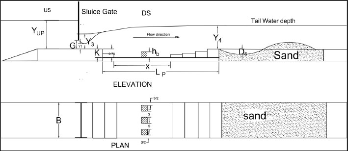
Definition sketches for the experimental model.
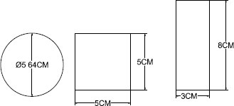
Different shapes of baffle blocks.
where: B is channel width; Lp is the stepped stilling basin length; G is the gate opening; K is the stepped stilling basin height; Wb is the block width; Lb is the block length; hb is the block height; Ds is the scour hole depth; Yup is the upstream water level; Y1 is the initial water depth; Y3 is the backwater depth; Y4 is the depth of water at the end of the submerged jump; D50 is the median grain size; g is the gravitational acceleration; VG is the velocity under the gate; V1 is the velocity at vena contraction; V4 is the velocity at the end of the hydraulic jump; ρ is the mass density of water; μ is the dynamic viscosity of water; ρs is the mass density of soil.
By applying Buckingham’s π-theorem and selecting ρ, G, VG as repeating variables, Eq. (1) can be expressed in dimensionless form as shown in Eq.(2):
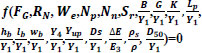 ...(2)
The effects of
 were excluded because only one fluid and one soil were used. The channel (B), gate opening (G), stepped stilling basin, length (Lp), stepped stilling basin height (K), and area of block A= (lb * wb) were kept constant. The effect of the Reynolds number,
 , was neglected, as viscosity has a negligible influence on the characteristics of hydraulic jumps.
 , using a surface tension standard value for clean water at room temperature, coefficient of σ = 0.072 N/m. Weber number is large (We>>1), making viscous and surface tension effects negligible. Therefore, as in other experimental studies, Reynolds and Weber numbers were omitted in this work, as their influence was considered insignificant under the present flow conditions [31].
Hence, Eq. (2) can be reduced to Eq. (3) as follows:
 ...(3)
The relative energy dissipation through the hydraulic jump can be expressed by Eqs. (4 to 6):
 ...(4)
 ...(5)
 ...(6)
where:
 is the maximum relative scour depth,
 is the densimetric particle Froude number with V cross-sectional mean velocity, g modified gravitational acceleration,
 is the Froude number under the gate,
 is the velocity just downstream of the gate, Nn is the number of negative steps, where NP is the number of positive steps, Nb is the number of baffle blocks,
 is the relative block height,
 : is the relative upstream water level,
 is the relative sequent water depth, Sr =
 is the relative submerged water depth, and
 is the relative blockage ratio.
2.2. Experimental Flume Setup
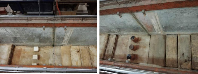
The experiments were conducted in the Hydraulic and Water Engineering Laboratory at the Faculty of Engineering, Zagazig University, Egypt. A recirculating laboratory flume of 15.6 m length, 0.30 m width, and 0.468 m depth was used for the trials, as shown in Fig. (3). Discharges were measured using a pre-calibrated orifice meter installed in the feeding pipeline. The stilling basin model was made of marble; the steps and blocks were constructed from wood, as shown in Fig. (4). Stepped stilling basin dimensions: Length (Lp), width (B), and depth (K) are 100, 30, and 5 cm, respectively. The dimensions of the stepped stilling basin were adopted from the experimental work of Negm and Abdel-Aal [14]. The step height (K) should be less than the critical height to avoid surface jump in the basin (Jiang and Diao [15]). The tailgate at the end of the flume was used to control the tail water depth. During the experiments, the tailgate was controlled such that the submergence ratio (Sr =
) was set to 3.3. The submerged hydraulic jump was selected because it frequently occurs downstream of sluice gates under increased tailwater conditions [14, 32]. The applied discharges corresponded to Froude numbers ranging from 1.0 to 2.0.
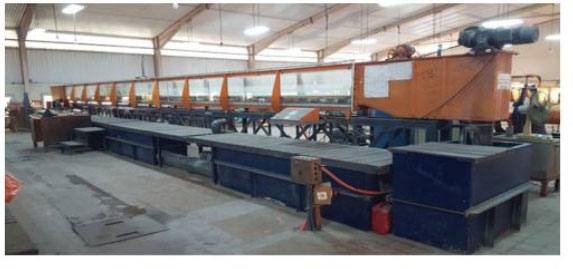
A general view of the flume.
Plan of the experimental models.
2.3. Soil Properties of Bed Material
The removable bed is composed of uniform natural sand, 0.1 m deep and 2.0 m long, formed downstream of the stepped stilling basin. The total length of the movable bed channel used in the present study (2m) is consistent with the channel length employed by Daneshfaraz and Mehrivar [33]. The soil has a median diameter d50 of 0.66 mm; Fig. (5), the geometrical deviation,
 , was 2.33, where d50%, d84%, and d16% represent the sieve openings that allow 50%, 84%, and 16% of the sediment particles to pass, respectively. The sediment used in the downstream erodible bed was uniform sand, characterized by a median grain size of d50 of 0.66 mm. The selection criteria were based on previous experimental studies [34]. Using d50 ensures reproducibility, simplifies comparison with other research, and reflects the dominant particle size controlling the initiation and development of local scour.
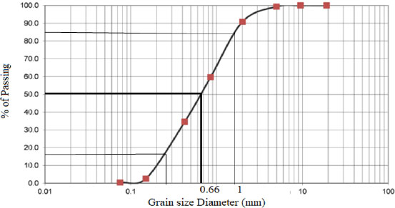
Particle size distribution for particle bed.
2.4. Experimental Procedure
The experimental procedure was as follows: (1) the sand bed surface was leveled by a plate attached to the carriage; (2) the tested model was fixed in the flume; (3) the gate opening was set at 4.5 cm; (4) the pump was switched on and the required discharge was gradually achieved using the control valve; (5) the tailgate was adjusted to ensure the desired submergence condition was attained; (6) The run time was initiated, and the scour process was observed until complete stability was reached after 120 minutes which is required to reach 85% of the maximum scour depth, shown in Fig. (6), and then the tailgate was fully opened to drain the water. After the water was completely drained, the scour hole profile was measured using a point gauge with an accuracy of ±0.1 mm. The movable bed topography was measured at 5 cm intervals in both the longitudinal (x) and transverse (y) directions to characterize the scour pattern.
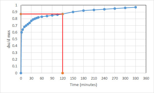
The time curve of the runs.
The experimental work in this study was carried out over 16 models (Tables 1 and 2), with each set constrained to the same submergence ratio (sr =3.3), and a range of Froude numbers from 1.0 to 2.0 as detailed below:
| Models | Description | Models | Description |
|---|---|---|---|
| A | 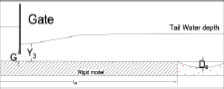 |
C1 | 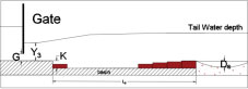 |
| B1 | 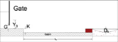 |
C2 | 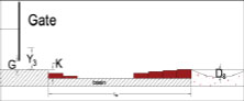 |
| B2 | 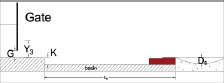 |
Model E | 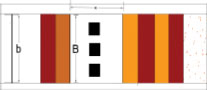 |
| B3 | 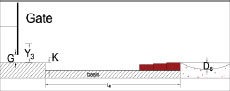 |
Model F | 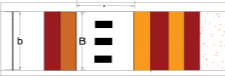 |
| B4 | 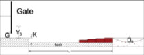 |
Model G | 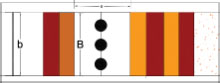 |
| Test No. |
Model Description |
No of Negative Step |
No of Positive Step |
Y3 (m) | FG(-) | Fd(-) | Ds(m) | Ds/Y1 | Y4(m) | E3(m) | E4(m) |

|
|---|---|---|---|---|---|---|---|---|---|---|---|---|
| 1 |
A: Flat Basin |
0 | 0 | 0.1 | 1.31 | 12.1 | 0.023 | 0.76 | 1.39 | 0.18 | 0.14 | 20.84 |
| 2 | 0.1 | 1.43 | 13.3 | 0.030 | 1.00 | 1.40 | 0.20 | 0.14 | 26.30 | |||
| 3 | 0.1 | 1.56 | 14.5 | 0.038 | 1.26 | 1.59 | 0.21 | 0.16 | 23.74 | |||
| 4 | 0.1 | 1.67 | 15.5 | 0.042 | 1.39 | 1.60 | 0.23 | 0.16 | 28.63 | |||
| 5 | 0.1 | 1.79 | 16.6 | 0.053 | 1.76 | 1.75 | 0.25 | 0.18 | 28.22 | |||
| 6 | 0.1 | 2.01 | 18.6 | 0.065 | 2.16 | 1.85 | 0.29 | 0.19 | 34.26 | |||
| 7 | 0.1 | 2.12 | 19.7 | 0.075 | 2.49 | 1.89 | 0.31 | 0.19 | 37.46 | |||
| 8 |
B1: One Positive Step |
1 | 1 | 0.1 | 1.19 | 11.0 | 0.031 | 1.03 | 1.34 | 0.17 | 0.14 | 17.39 |
| 9 | 0.1 | 1.28 | 11.9 | 0.033 | 1.09 | 1.39 | 0.18 | 0.14 | 19.38 | |||
| 10 | 0.1 | 1.31 | 12.2 | 0.034 | 1.13 | 1.40 | 0.18 | 0.14 | 20.44 | |||
| 11 | 0.1 | 1.55 | 14.4 | 0.037 | 1.23 | 1.50 | 0.21 | 0.15 | 27.33 | |||
| 12 | 0.1 | 1.81 | 16.8 | 0.042 | 1.39 | 1.59 | 0.25 | 0.16 | 34.99 | |||
| 13 | 0.1 | 2.02 | 18.7 | 0.052 | 1.72 | 1.64 | 0.29 | 0.17 | 41.40 | |||
| 14 |
B2: Two Positive Steps |
1 | 2 | 0.1 | 1.18 | 10.9 | 0.028 | 0.93 | 1.26 | 0.16 | 0.13 | 21.28 |
| 15 | 0.1 | 1.19 | 11.1 | 0.029 | 0.96 | 1.28 | 0.17 | .0.13 | 20.98 | |||
| 16 | 0.1 | 1.31 | 12.2 | 0.030 | 1.00 | 1.30 | 0.18 | 0.13 | 25.64 | |||
| 17 | 0.1 | 1.55 | 14.4 | 0.033 | 1.09 | 1.40 | 0.21 | 0.15 | 31.71 | |||
| 18 | 0.1 | 1.82 | 16.9 | 0.038 | 1.26 | 1.54 | 0.25 | 0.16 | 37.24 | |||
| 19 | 0.1 | 1.98 | 18.4 | 0.041 | 1.36 | 1.64 | 0.28 | 0.17 | 40.01 | |||
| 20 |
B3: Three Positive Steps |
1 | 3 | 0.1 | 1.17 | 10.8 | 0.028 | 0.93 | 1.30 | 0.16 | 0.13 | 18.65 |
| 21 | 0.1 | 1.31 | 12.1 | 0.030 | 1.00 | 1.32 | 0.18 | 0.14 | 24.50 | |||
| 22 | 0.1 | 1.34 | 12.4 | 0.030 | 1.00 | 1.40 | 0.18 | 0.14 | 21.71 | |||
| 23 | 0.1 | 1.58 | 14.6 | 0.033 | 1.09 | 1.55 | 0.22 | 0.16 | 26.26 | |||
| 24 | 0.1 | 1.84 | 17.1 | 0.037 | 1.23 | 1.65 | 0.26 | 0.17 | 34.13 | |||
| 25 | 0.1 | 1.94 | 17.9 | 0.045 | 1.49 | 1.72 | 0.27 | 0.18 | 35.49 | |||
| 26 |
B4: Four Positive Steps |
1 | 4 | 0.1 | 1.16 | 10.8 | 0.025 | 0.83 | 1.30 | 0.16 | 0.13 | 18.16 |
| 27 | 0.1 | 1.22 | 11.3 | 0.026 | 0.86 | 1.35 | 0.17 | 0.13 | 21.44 | |||
| 28 | 0.1 | 1.27 | 11.8 | 0.026 | 0.86 | 1.37 | 0.18 | 0.14 | 20.86 | |||
| 29 | 0.1 | 1.43 | 13.3 | 0.030 | 1.00 | 1.44 | 0.20 | 0.14 | 28.01 | |||
| 30 | 0.1 | 1.62 | 15.0 | 0.035 | 1.16 | 1.50 | 0.22 | 0.15 | 33.13 | |||
| 31 | 0.1 | 1.69 | 15.7 | 0.036 | 1.19 | 1.56 | 0.23 | 0.15 | 33.62 | |||
| 32 | 0.1 | 1.95 | 18.1 | 0.038 | 1.26 | 1.63 | 0.28 | 0.16 | 41.74 | |||
| 33 | 0.1 | 2.02 | 18.7 | 0.039 | 1.29 | 1.74 | 0.29 | 0.18 | 38.21 | |||
| 34 |
C1: two Negative step |
2 | 4 | 0.1 | 1.15 | 10.6 | 0.023 | 0.76 | 1.18 | 0.16 | 0.12 | 24.42 |
| 35 | 0.1 | 1.24 | 11.5 | 0.024 | 0.80 | 1.20 | 0.17 | 0.12 | 27.47 | |||
| 36 | 0.1 | 1.55 | 14.4 | 0.030 | 1.00 | 1.42 | 0.21 | 0.15 | 30.84 | |||
| 37 | 0.1 | 1.67 | 15.5 | 0.035 | 1.16 | 1.50 | 0.23 | 0.16 | 32.68 | |||
| 38 | 0.1 | 1.79 | 16.6 | 0.036 | 1.19 | 1.58 | 0.25 | 0.16 | 34.47 | |||
| 39 | 0.1 | 1.91 | 17.7 | 0.037 | 1.23 | 1.60 | 0.27 | 0.17 | 38.65 | |||
| 40 |
C2: Three negative step |
3 | 4 | 0.1 | 1.19 | 11.0 | 0.028 | 0.93 | 1.30 | 0.17 | 0.13 | 19.73 |
| 41 | 0.1 | 1.30 | 12.0 | 0.028 | 0.93 | 1.32 | 0.18 | 0.14 | 23.81 | |||
| 42 | 0.1 | 1.50 | 13.9 | 0.035 | 1.16 | 1.40 | 0.21 | 0.14 | 29.33 | |||
| 43 | 0.1 | 1.60 | 14.8 | 0.036 | 1.19 | 1.52 | 0.22 | 0.16 | 28.51 | |||
| 44 | 0.1 | 1.82 | 16.9 | 0.038 | 1.26 | 1.60 | 0.25 | 0.17 | 35.06 | |||
| 45 | 0.1 | 1.91 | 17.7 | 0.038 | 1.26 | 1.61 | 0.27 | 0.17 | 38.31 |
- Model A (Reference case): A flat floor without any steps or baffles was adopted as the baseline for comparison.
- Model B (Positive and negative step arrangements): Four scenarios were considered, consisting of a single negative step followed by a varying number of positive steps:
- B1: one negative step followed by one positive step.
- B2: one negative step followed by two positive steps.
- B3: one negative step followed by three positive steps.
- B4: one negative step followed by four positive steps.
- Model C (Multiple negative step arrangements): Two scenarios were examined, including:
- C1: two consecutive negative steps followed by four positive steps.
- C2: three consecutive negative steps followed by four positive steps.
- Three different block configurations Square, rectangular, and cylinder (E, F, and G) with varying relative heights (h/k= 0.5, 1.0, and 1.5) were investigated.
2.5. The Scale Effect
In the present study, some parameters with minor influence were not considered due to the experimental scale. For example, the channel sidewalls were made of Perspex with a smooth surface, so wall friction was negligible compared with the bed resistance. The flume width was selected to be sufficiently larger than the flow depth and the baffle block dimensions, thereby minimizing sidewall interference. The use of a submerged hydraulic jump also contributed to reducing the sidewall influence by confining a greater portion of the flow vertically. Scale effects are inherent in physical hydraulic models because it is not possible to simultaneously satisfy all similarity criteria, particularly the Froude and Reynolds criteria. These effects can significantly influence turbulence characteristics, air entrainment, and energy dissipation in hydraulic jumps [31].
| Test No. |
Mode Description |
No of Negative Step |
No of Positive Step |
No of Rows |
Relative Block Height (h/k) |
Y3(m) | FG(-) | Fd(-) | DS(m) |

|
Y4(m) | E3(m) | E4(m) |

|
|---|---|---|---|---|---|---|---|---|---|---|---|---|---|---|
| 46 |
E1: Square block (h/k=0.5) |
2 | 4 | 1 | 0.5 | 0.1 | 1.16 | 10.73 | 0.02 | 0.66 | 0.12 | 0.16 | 0.12 | 23.82 |
| 47 | 0.1 | 1.27 | 11.75 | 0.02 | 0.66 | 0.124 | 0.18 | 0.13 | 26.68 | |||||
| 48 | 0.1 | 1.47 | 13.65 | 0.03 | 0.83 | 0.135 | 0.20 | 0.14 | 30.50 | |||||
| 49 | 0.1 | 1.59 | 14.68 | 0.03 | 1.09 | 0.15 | 0.22 | 0.15 | 28.82 | |||||
| 50 | 0.1 | 1.69 | 15.64 | 0.04 | 1.19 | 0.156 | 0.23 | 0.16 | 31.00 | |||||
| 51 | 0.1 | 1.79 | 16.60 | 0.04 | 1.19 | 0.16 | 0.25 | 0.17 | 33.87 | |||||
| 52 | 0.1 | 1.92 | 17.81 | 0.04 | 1.23 | 0.163 | 0.27 | 0.17 | 38.09 | |||||
| 53 |
E2: square block (h/k=1) |
2 | 4 | 1 | 1 | 0.1 | 1.14 | 10.60 | 0.02 | 0.66 | 0.124 | 0.16 | 0.13 | 20.83 |
| 54 | 0.1 | 1.27 | 11.78 | 0.025 | 0.83 | 0.13 | 0.18 | 0.13 | 23.66 | |||||
| 55 | 0.1 | 1.31 | 12.17 | 0.025 | 0.83 | 0.14 | 0.18 | 0.14 | 20.44 | |||||
| 56 | 0.1 | 1.47 | 13.65 | 0.03 | 0.86 | 0.144 | 0.20 | 0.15 | 26.34 | |||||
| 57 | 0.1 | 1.66 | 15.33 | 0.03 | 1.00 | 0.156 | 0.23 | 0.16 | 29.50 | |||||
| 58 | 0.1 | 1.89 | 17.54 | 0.03 | 1.09 | 0.163 | 0.27 | 0.17 | 36.92 | |||||
| 59 | 0.1 | 1.91 | 17.70 | 0.03 | 1.09 | 0.17 | 0.27 | 0.18 | 35.21 | |||||
| 60 |
E2: square block (h/k=1.5) |
2 | 4 | 1 | 1.5 | 0.1 | 1.11 | 10.31 | 0.02 | 0.50 | 0.13 | 0.16 | 0.13 | 15.70 |
| 61 | 0.1 | 1.24 | 11.47 | 0.02 | 0.66 | 0.135 | 0.17 | 0.14 | 19.29 | |||||
| 62 | 0.1 | 1.37 | 12.67 | 0.02 | 0.73 | 0.139 | 0.19 | 0.14 | 23.64 | |||||
| 63 | 0.1 | 1.55 | 14.38 | 0.03 | 0.83 | 0.139 | 0.21 | 0.14 | 32.15 | |||||
| 64 | 0.1 | 1.71 | 15.85 | 0.03 | 1.00 | 0.156 | 0.24 | 0.16 | 31.99 | |||||
| 65 | 0.1 | 1.87 | 17.35 | 0.03 | 1.06 | 0.17 | 0.26 | 0.18 | 33.63 | |||||
| 66 | 0.1 | 1.96 | 18.18 | 0.04 | 1.16 | 0.177 | 0.28 | 0.18 | 34.91 | |||||
| 67 |
F1:Rectangular block (h/k=0.5) |
2 | 4 | 1 | 0.5 | 0.1 | 1.21 | 11.19 | 0.03 | 0.83 | 0.135 | 0.17 | 0.14 | 17.69 |
| 68 | 0.1 | 1.38 | 12.79 | 0.03 | 0.93 | 0.143 | 0.19 | 0.15 | 22.28 | |||||
| 69 | 0.1 | 1.60 | 14.79 | 0.03 | 1.03 | 0.148 | 0.22 | 0.15 | 30.22 | |||||
| 70 | 0.1 | 1.71 | 15.85 | 0.03 | 1.13 | 0.159 | 0.24 | 0.16 | 30.81 | |||||
| 71 | 0.1 | 1.92 | 17.81 | 0.04 | 1.16 | 0.165 | 0.27 | 0.17 | 37.40 | |||||
| 72 |
F2:Rectangular block (h/k=1) |
2 | 4 | 1 | 1 | 0.1 | 1.19 | 11.04 | 0.03 | 0.83 | 0.132 | 0.17 | 0.14 | 18.59 |
| 73 | 0.1 | 1.34 | 12.41 | 0.03 | 0.93 | 0.14 | 0.18 | 0.14 | 21.77 | |||||
| 74 | 0.1 | 1.55 | 14.35 | 0.03 | 1.13 | 0.148 | 0.21 | 0.15 | 28.05 | |||||
| 75 | 0.1 | 1.71 | 15.85 | 0.04 | 1.16 | 0.155 | 0.24 | 0.16 | 32.39 | |||||
| 76 | 0.1 | 1.82 | 16.86 | 0.04 | 1.26 | 0.164 | 0.25 | 0.17 | 33.59 | |||||
| 77 |
F3:Rectangular block (h/k=1.5) |
2 | 4 | 1 | 1.5 | 0.1 | 1.31 | 12.15 | 0.03 | 0.83 | 0.14 | 0.18 | 0.14 | 20.32 |
| 78 | 0.1 | 1.42 | 13.17 | 0.03 | 0.93 | 0.145 | 0.19 | 0.15 | 23.32 | |||||
| 79 | 0.1 | 1.52 | 14.12 | 0.03 | 1.03 | 0.149 | 0.21 | 0.15 | 26.42 | |||||
| 80 | 0.1 | 1.71 | 15.85 | 0.03 | 1.13 | 0.16 | 0.24 | 0.16 | 30.41 | |||||
| 81 | 0.1 | 1.81 | 16.76 | 0.04 | 1.16 | 0.163 | 0.25 | 0.17 | 33.51 | |||||
| 82 |
G1:Cylindrical block (h/k=0.5) |
2 | 4 | 1 | 0.5 | 0.1 | 1.19 | 11.04 | 0.02 | 0.66 | 0.135 | 0.17 | 0.138312 | 16.88 |
| 83 | 0.1 | 1.27 | 11.75 | 0.025 | 0.83 | 0.13 | 0.18 | 0.134045 | 23.49 | |||||
| 84 | 0.1 | 1.42 | 13.17 | 0.033 | 1.09 | 0.144 | 0.19 | 0.148139 | 23.80 | |||||
| 85 | 0.1 | 1.60 | 14.79 | 0.036 | 1.19 | 0.15 | 0.22 | 0.154815 | 29.37 | |||||
| 86 | 0.1 | 1.86 | 17.26 | 0.025 | 0.83 | 0.165 | 0.26 | 0.170417 | 35.02 | |||||
| 87 |
G2: Cylindrical block (h/k=1) |
2 | 4 | 1 | 1 | 0.1 | 1.19 | 11.05 | 0.022 | 0.73 | 0.132 | 0.17 | 0.135471 | 18.65 |
| 88 | 0.1 | 1.37 | 12.67 | 0.028 | 0.93 | 0.139 | 0.19 | 0.143112 | 23.64 | |||||
| 89 | 0.1 | 1.52 | 14.12 | 0.032 | 1.06 | 0.148 | 0.21 | 0.152505 | 26.87 | |||||
| 90 | 0.1 | 1.60 | 14.79 | 0.035 | 1.16 | 0.15 | 0.22 | 0.154815 | 29.37 | |||||
| 91 | 0.1 | 1.92 | 17.81 | 0.037 | 1.23 | 0.161 | 0.27 | 0.16706 | 38.76 | |||||
| 92 |
G3:Cylindrical block (h/k=1.5) |
2 | 4 | 1 | 1.5 | 0.1 | 1.16 | 10.75 | 0.025 | 0.83 | 0.128 | 0.16 | 0.131495 | 19.32 |
| 93 | 0.1 | 1.34 | 12.41 | 0.025 | 0.83 | 0.141 | 0.18 | 0.144838 | 21.25 | |||||
| 94 | 0.1 | 1.47 | 13.65 | 0.033 | 1.09 | 0.14 | 0.20 | 0.144708 | 28.19 | |||||
| 95 | 0.1 | 1.76 | 16.26 | 0.035 | 1.16 | 0.162 | 0.24 | 0.16699 | 31.58 | |||||
| 96 | 0.1 | 1.92 | 17.81 | 0.038 | 1.26 | 0.165 | 0.27 | 0.17077 | 37.40 |
3. RESULTS AND DISCUSSION
3.1. Effect of Stepped Stilling Basin with Negative and Positive Steps
Three different models, a flat basin (model A) and a stepped stilling basin with negative and positive steps (models B and C), shown in Table 2, were tested to minimize the scouring depth. For each design, five different discharges were tested, leading to upstream and downstream levels. Tailwater depth was adjusted to obtain a constant submergence ratio (Sr=3.3). The adopted configurations, including both negative and positive steps, are consistent with classical studies on hydraulic jumps over stepped basins. Hager and Bretz [35] demonstrated that step geometry, whether positive or negative, plays a crucial role in controlling flow patterns, turbulence characteristics, and energy dissipation efficiency.
Three different parameters, the local scour depth
 , energy dissipation efficiency
 , and sequent depth ratio
 were investigated experimentally under various basin configurations to enable a consistent comparison across different hydraulic conditions.
3.1.1. Energy Dissipation Efficiency

The efficiency of energy dissipation,
 ; increased with the gate Froude number, FG for all designs as shown in Fig. (7). The relative improvement increased by 3%, 6%, 12%, 24%, 18%, and 9% for models B1, B2, B3, B4, C1, and C2, respectively, compared with the flat basin (model A) at FG=1.91, as shown in Fig. (8). This limited effect is attributed to the occurrence of a submerged hydraulic jump, where reduced turbulence and air entrainment significantly lowered the dissipation efficiency. Similar observations were reported by Kumar Jayant and Jhamnani [36], Choi and Choi [37], and Jahad and Chabuk [38], who confirmed that the limited improvement in energy dissipation in positive-stepped models is due to the submerged hydraulic jump, which is inherently less efficient than a free jump.
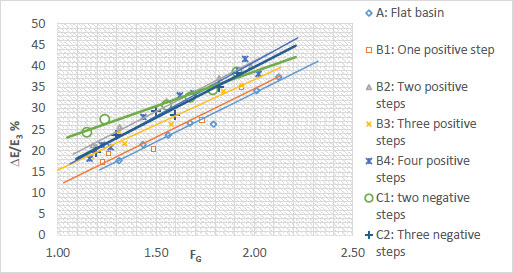
Relationship between relative ratio of energy dissipation (
) and gate froude number (FG) for different basin configuration.
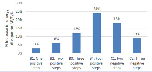
Percentage increase in relative energy dissipation of different pooled basin models with positive and negative steps compared with the flat basin at FG =1.91.
3.1.2. Scour Depth Ratio

The scour water depth ratio;
 increased as the gate Froude number, FG, increased as shown in Fig. (9). The results for all cases of the stepped stilling basin with negative and positive steps minimize scour depth compared to the reference case, which corresponds to the flat floor with no steps.
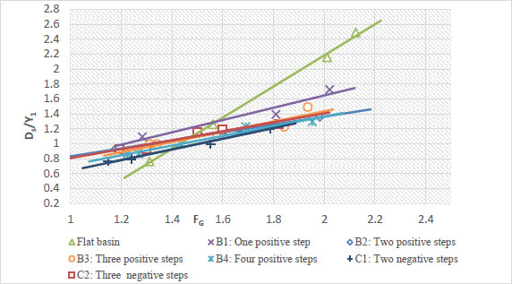
Effects of different shapes, B, C, and the flat basin model A, on maximum scour depth.
At FG=1.91, the maximum relative scour depth decreases by 20%, 37%,31%, 40%, 48%, and 40% for models B1, B2, B3, B4, C1, and C2, respectively, compared to model A as shown in Fig. (10). Ali and Mohamed [19] confirm that incorporating positive steps in the stilling basin significantly improves the hydraulic performance downstream of the gate.
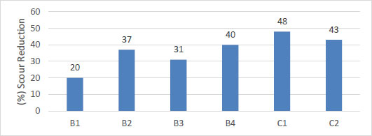
Reduction percentage of relative scour depths of different pooled basin models with positive and negative steps compared with the flat basin at FG =1.91.
3.1.3. Sequent Depth Ratio

Figure 11 illustrates the variation of the sequent depth ratio
with the gate Froude number (FG) for different basin configurations. In all cases,
 increases as FG increases, indicating that higher inflow momentum produces a deeper downstream sequent depth. Among all designs, the stepped stilling basin with two negative steps (C1) followed by four positive steps yield the highest,
ratios, the hydraulic performance was improved, as indicated by the reduction in scour depth.
increases as FG increases, indicating that higher inflow momentum produces a deeper downstream sequent depth. Among all designs, the stepped stilling basin with two negative steps (C1) followed by four positive steps yield the highest,
ratios, the hydraulic performance was improved, as indicated by the reduction in scour depth.
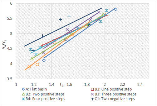
Relationship between Relative Depth Ratio (Y4/Y1) and Gate Froude Number (FG) for Different Basin Configuration.
Although C1 and C2 did not record the highest total energy dissipation
 , they achieved the lowest scour depth ratios
. This is because scour is primarily governed by the residual bed velocity downstream of the basin, which reflects the remaining kinetic energy, whereas
measures the total energy loss, including both kinetic and potential components. In negative-step designs, such as C1 and C2, a substantial portion of the kinetic energy is dissipated within the basin through vortex formation and turbulent mixing before the flow reaches the scour zone. This interpretation is supported by the
results, where higher sequent depth ratios were observed for C1 and C2, indicating lower downstream velocities and reduced residual kinetic energy. Consequently, the bed velocity and associated scour are minimized, even though the total energy loss is not the highest compared to other configurations.
, they achieved the lowest scour depth ratios
. This is because scour is primarily governed by the residual bed velocity downstream of the basin, which reflects the remaining kinetic energy, whereas
measures the total energy loss, including both kinetic and potential components. In negative-step designs, such as C1 and C2, a substantial portion of the kinetic energy is dissipated within the basin through vortex formation and turbulent mixing before the flow reaches the scour zone. This interpretation is supported by the
results, where higher sequent depth ratios were observed for C1 and C2, indicating lower downstream velocities and reduced residual kinetic energy. Consequently, the bed velocity and associated scour are minimized, even though the total energy loss is not the highest compared to other configurations.
Figure 12 shows the scour hole profiles for various tests conducted at a Froude number of 1.91.
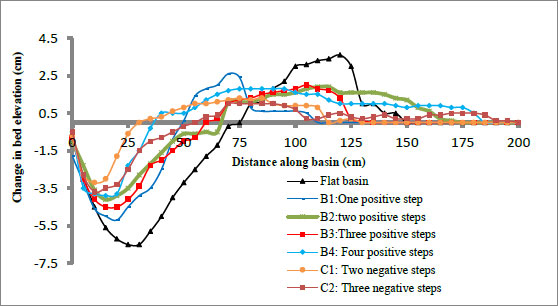
Effect of step configuration on bed elevation change along the flume and the flat basin model at FG 1.91.
3.2. Effect of Adding Baffle Blocks to the Stepped Stilling Basin
In this study, three different block configurations (Square, rectangular, and cylinder) with varying relative heights (
 = 0.5, 1.0, and 1.5) were investigated to identify the optimal block shape and height that achieves a balance between energy dissipation within the stepped poled basin and the reduction of local scour downstream. A single-row arrangement was adopted based on previous studies, which showed fewer fluctuations along the channel centerline than double-row arrangements. In contrast, double rows increase surface turbulence and reduce overall energy dissipation efficiency due to upstream water level rise and downstream flow acceleration. The reason for this is that the water level increased slightly upstream in the double-row array and the flow velocity increased after the blocks [39, 40].
3.2.1. The Effect of Baffle Block Height
Figure 13 illustrates the relationship between the relative energy dissipation
and the gate Froude number (FG), showing the block height influence on the dissipation efficiency.
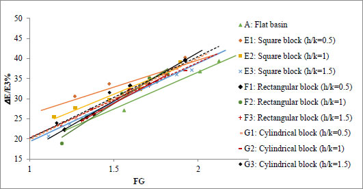
Effects of the shapes and relative height of baffle blocks on energy dissipation efficiency with the gate Froude number (fG).
Figure 14 demonstrates the relationship between the relative maximum scour depth
and the gate Froude number (FG) to examine the effect of baffle block height with relative heights (
= 0.5,1,1.5) across different shapes: rectangular, square, and cylindrical (models F, E, and G). It was observed that the relative scour depth
increases with an increase in the gate Froude number (FG).
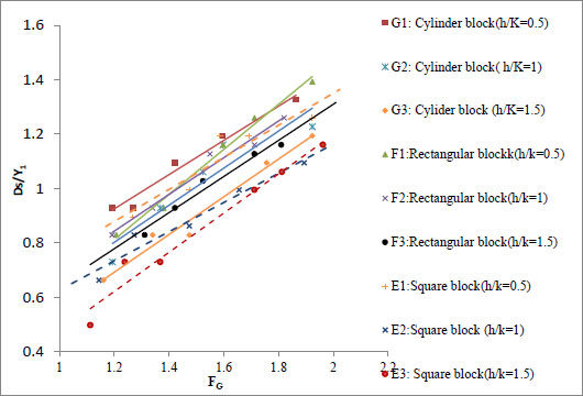
Effects of the shapes and relative height of baffle blocks on the relative scour depth with the gate Froude number (FG).
Figure 15 illustrates the variation of the relative sequent water depth
with the gate Froude number (FG). Measuring the relative sequent water depth
reflects the flow depth variation downstream of the basin and provides an indirect measure of the residual flow velocity at the exit section. Since scour and sediment transport are primarily governed by the velocity near the bed, the ratio
becomes a valuable indicator of the basin’s ability to stabilize the flow. A higher relative depth generally implies reduced exit velocity and therefore better protection against bed erosion.
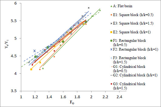
Effects of the shapes and relative height of baffle blocks on relative sequent water depth (Y1/Y4) with the gate Froude number (FG).
The experimental results illustrate that the baffle block height plays a decisive role in hydraulic performance. Taller blocks (
= 1.5) reduced scour depth effectively because they suppressed the bed velocities near the bed and dissipated the residual kinetic energy responsible for local erosion. In contrast, shorter blocks (
= 0.5) achieved higher energy dissipation within the stilling basin by generating intense turbulence and vortices, yet did not significantly reduce the downstream bed shear stress. Therefore, the optimal block height depends on whether the design priority is minimizing local scour or maximizing energy dissipation within the basin.
Previous studies (Wu and Rajaratnam [41], Habibzadeh and Wu [42], Zaffar, Haasan [26]) have consistently reported that higher energy dissipation does not always correspond to lower scour depths. This discrepancy arises because energy dissipation accounts for the overall loss of both potential and kinetic energy, whereas scour is mainly governed by the residual flow conditions at the basin exit, particularly the near-bed velocity and shear stress. As a result, designs that strongly dissipate energy through turbulence may still allow sufficient residual momentum to cause local erosion.
Energy dissipation and scour reduction should be viewed as complementary but separate goals from a design standpoint. To prevent general scour, structural vibrations, and excessive basin length, adequate energy dissipation is crucial for overall downstream safety. However, reducing local scour lowers maintenance costs and guarantees stability at the immediate basin outflow. Therefore, an intermediate block height (
= 1.0) often provides a practical compromise, ensuring sufficient energy loss within the basin while also limiting residual velocities that drive local scour.
Abdelaal and Eltohamy [43] emphasized that the most effective block sill height is close to the critical depth (YCritical), as excessive heights tend to deflect the jet excessively, reducing turbulence and lowering dissipation efficiency. The selected step heights represent a practical range from low to high obstruction conditions, covering values below, around, and above the optimum height, which is typically close to the critical depth.
3.2.2. The Effect of Baffle Block Shape
The results demonstrate that block geometry strongly influences both energy dissipation and scour reduction. Square blocks, particularly with relative height ratios of
=1, 1.5 (E2 and E3), achieved the best overall performance: they generated high energy dissipation comparable to or even exceeding cylindrical blocks, while simultaneously reducing downstream scour due to their ability to increase the flow depth ratio
and weaken near-bed velocities.
Rectangular and cylindrical blocks also enhanced energy dissipation, but they were less effective in minimizing scour, as their induced vortices transmitted higher residual velocities toward the bed. Therefore, the square block is identified as the most efficient geometry, offering a balanced solution that maximizes energy dissipation while minimizing scour risk.
It is observed that the square, cylindrical, and rectangular shapes reduce the maximum scour depth by 54%, 47%, and 44%, respectively, at a Froude number of 1.91 with a relative height of (
=1.5).
Figure 16 illustrates flow patterns around different obstacle shapes. It's observed that:
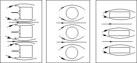
Flow directions of different shapes.
- In the square shape, sharp corners cause strong flow separation, forming a reverse wave that increases energy dispersion and reduces erosion.
- In the case of the cylindrical shape, the flow is more gently directed, though the effect of the width remains unchanged.
- The rectangular shape, with a more elongated shape, shows intermediate behavior, and the wake zone appears more confined than in the square shape.
Figure 17 shows the relative scour depth versus longitudinal distance beyond the stepped basin for different shapes, E2, F2, G2, and a flat basin at relative block height (
=1.5) and FG = 1.91.
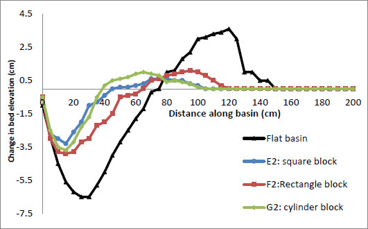
Relative scour depth versus longitudinal distance beyond stepped basin for different shapes E2, F2, G2, and flat basin at relative block height (
= 1.5) and FG= 1.91.
Figure 18 illustrates the reduction percentage of relative scour depth for various cases in this study, based on the flat bed model at FG= 1.91. The results show that adding a single raw block with a relative height (
=1.5) to the stepped stilling basin, which has two negative steps followed by four positive steps, increased the reduction percentage to 44%, 47%, and 54% for circular, rectangular, and square shapes (Models G3, F3, and E3), respectively.
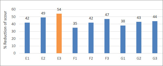
Reduction percentage of relative scour depths for pooled basins with baffle blocks of different configurations compared with the flat basin at FG = 1.91.
Although energy dissipation improvements among configurations, shown in Fig. (19), are relatively small, the square block at
=1.5 produced a substantially larger reduction in scour depth; therefore, when scour mitigation is prioritized, this configuration is recommended.
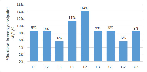
Percentage increase in relative energy dissipation for pooled basins with baffle blocks of different configurations compared with the flat basin at FG=1.91
3.3. Prediction of Scour Hole Dimensions
The prediction of the relative scour depth
downstream of stepped stilling basins with negative steps, positive steps, and baffle blocks with three different shapes; rectangular, square, and cylindrical; was carried out using the current experimental data to develop empirical equations through statistical methods. The scour estimation model was calibrated using 60% of the experimental data and validated with the remaining 40%. The regression coefficients (C0, C1, and C2,) were estimated using the least squares method, based on the datasets of (a) rectangular baffle block, (b) cylindrical baffle block, (c) square baffle block, (Table 3). Substituting the obtained regression coefficients into Eq. (7) yielded Eq. (8) for case (a), Eq. (9) for case (b), and Eq. (10) for case (C). The equations are applicable only within the tested discharge range and the tested structural configurations (stepped stilling basin with positive and negative steps and baffle blocks). Parameters, such as the Reynolds and Weber numbers, were neglected due to their minor influence at the model scale. Therefore, the proposed relations should be applied cautiously and are not directly generalizable to prototype-scale conditions without further verification. Figure 20 shows the relationship between the measured and predicted data for different baffle block shapes. The associated errors for computing the maximum depths by Eq. (7) were consistent and did not exceed ± 4%, as shown in Table 3.
| Case | C0 | C1 | C3 | Multiple R | R Square | Adjusted R Square | Standard Error |
|---|---|---|---|---|---|---|---|
| (a) | 0.015 | 0.49 | -0.063 | 0.98 | 0.97 | 0.96 | 0.023 |
| (b) | 0.145 | 0.45 | -0.14 | 0.97 | 0.95 | 0.94 | 0.031 |
| (c) | 0.118 | 0.431 | -0.142 | 0.97 | 0.94 | 0.93 | 0.04 |
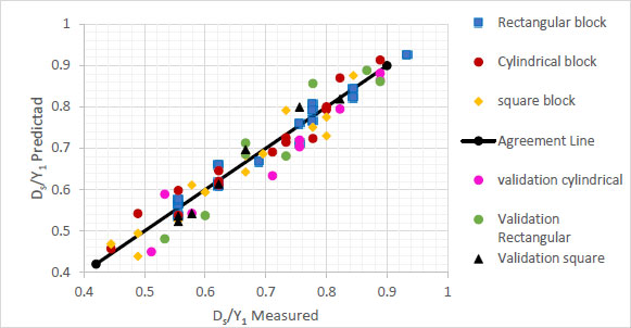
Relation between the measured and predicted data for different shapes of baffle blocks.
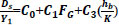 ...(7)
 ...(8)
 ...(9)
 ...(10)
4. LIMITATIONS AND FUTURE WORKS
Scale effects: Prototype sediment flow and turbulence may not be adequately captured at laboratory scale under Froude similarity.
Testing conditions: Sediment sizes, block designs, and limited step heights were investigated.
Sidewall influence: Scour patterns may still have been impacted by some lateral effects.
Simplifying the sediment: Unlike natural mixed or cohesive beds, uniform sand was utilized.
Future Work: To validate the equations and support useful design guidance, numerical and field-scale research under broader hydrological and sediment conditions is advised
CONCLUSION
This study, based on sixteen basin configurations, provides the following key findings:
-
Effect of Step Configuration
- Introducing negative and positive steps significantly improved hydraulic performance compared with the flat basin.
- The configuration of two negative steps followed by four positive steps (Model C1) achieved the largest scour reduction (up to 48%) due to enhanced turbulence and improved jump stability.
- Models with negative steps effectively dissipated kinetic energy within the basin before the flow reached the downstream bed.
- Despite not achieving the highest total energy dissipation, model C1 and C2 delivered the lowest residual velocities, demonstrating that total energy loss is not the sole determinant of scour protection.
- Higher
values in models C1 and C2 indicated improved jump stability and lower residual velocities, consistent with their superior scour control.
-
Effect of Baffle Block Height
- Increasing relative block height (
) enhanced scour reduction.
- Blocks of
=1.5 suppressed residual kinetic energy most effectively and minimized local scour.
- Shorter blocks (
= 0.5) produced strong turbulence and higher energy dissipation inside the basin but did not sufficiently reduce downstream shear stresses.
- Increasing relative block height (
-
Effect of Baffle Block Shape
- Block geometry strongly influenced hydraulic behavior.
- Square blocks provided the best overall performance, reducing scour by 54%, followed by cylindrical (47%) and rectangular (44%) blocks.
- Flow pattern observations revealed strong separation zones and reverse waves behind square blocks, increasing flow depth and reducing bed velocity.
-
Design Implications
- Energy dissipation and scour reduction should be considered complementary but separate design objectives.
- For practical engineering applications,
= 1.0–1.5 with square blocks offers the optimal balance between energy loss and scour protection.
- The study provides empirical evidence and regression relationships useful for designing compact, efficient stilling basins under submerged-jump conditions.
AUTHORS' CONTRIBUTIONS
The authors confirm their contributions to the paper as follows: S.A.N.: Performed the experimental work, data analysis, and manuscript preparation; All authors, W.A.F, M.M.I, and E.E.T., reviewed and approved the final manuscript.
LIST OF ABBREVIATIONS
| B | = Channel bed width (L) |
| Lp | = stepped stilling basin length (L) |
| Yup | = Upstream water level (L) |
| Y1 | = Initial water level (L) |
| Y3 | = Backwater depth (L) |
| Y4 | = The depth of water at the end of the submerged jump (L) |
| G | = Gate opening (L) |
| K | = stepped stilling basin height (L) |
| wb | = Block width (L) |
| Lb | = Block length (L) |
| hb | = Block height (L) |
| λ | = The relative blockage Ratio (-) |
| D50 | = Median grain size (L) |
| Ds | = Scour hole depth (L) |
| Sr | = Submergence ratio (-) |
| ρ | = Mass density of water (ML-3) |
| μ | = Dynamic viscosity of water (ML-1T-1) |
| ρs | = Mass density of water (ML-3) |
| VG | = The velocity under the gate (LT-1) |
| V1 | = The velocity at vena contraction (LT-1) |
| V4 | = The velocity at the end of the hydraulic jump (LT-1) |
| FG | = Gate Froude’s number (-) |
| Fd | = the densimetric particle Froude number with V cross-sectional flow velocity (-) |
| g` | = modified gravitational acceleration (LT-2) |
| we | = Webber number (-) |
| Re | = Reynolds number (-) |
AVAILABILITY OF DATA AND MATERIALS
All data generated or analyzed during this study are included in this published article.
ACKNOWLEDGEMENTS
Declared none.
DISCLOSURE
Part of this article has previously been published in Scour reduction downstream of a sluice gate using stepped basins under submerged hydraulic jump condition doi: https://doi.org/10.1007/s44533-025-00014-4.